Air-Cooled VW
Product Catalogues
VW Split Screen Van
VW Bay Window Van
VW Beetle
VW Type 3
VW Thing / Trekker
VW Karmann-Ghia
VW Engines T1+T4
VW Electrical
IGNITION SYSTEMS
TOOLS
Other (Non VW)
Product Catalogues
Air Cooled Porsche
Rover V8 Parts
Ford Kits
BMC Era Car Parts
Land Rover Kits
|
Fitting A Type 4 215mm Clutch / Flywheel Assembly To A 1970 1500 Gearbox
There are several clutch / flywheel options to fit a Type4 motor into a 1970 Beetle :
- Use a RARE genuine 200mm flywheel or a brand new (aftermarket) 200mm flywheel imported from the USA.
A standard 200mm Beetle Type1 engine clutch (or favoured after-market performance clutch) can then be used.
- Use an easy to find stock VW 215mm flywheel and clutch with a clutch adapter pad to enable the pre 1972 (smaller)
clutch release bearing to engage the clutch.
The adapter pad attaches to the thrust face of the clutch mechanism on the flywheel such that the necessary
extra surface area (on the inner diameter) is presented to the earlier (smaller) clutch release bearing.
- Use a 215mm flywheel and clutch with the post 1972 (larger) release bearing installed on the clutch release shaft
(the type that sits on a guide sleeve).

Here at www.volksbolts.com we opted for the 215mm Type4 clutch as this was affordable and available in plentiful
abundance to us at the time. We also opted to use the larger release bearing found on post 1972 VWs with the
guide sleeve as this design is more robust / generally superior. Also, our crank, flywheel, clutch and pulley wheel
had previously been dynamically balanced as a single unit - the adapter pad may have threw this balance out.
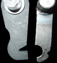
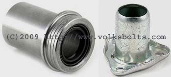
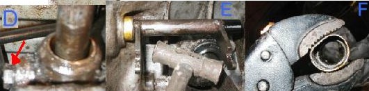
All good and simple you would think, but the release bearing fitted to our 1970 Beetle utilised the earlier
release forks design. This can be seen in the below picture : the post 1972 design being on the
left and the pre 1972 design on the right - both are orientated in the same installation direction - the
clutch / flywheel would be to the left.
The later (larger) bearing will not secure to the earlier forks.
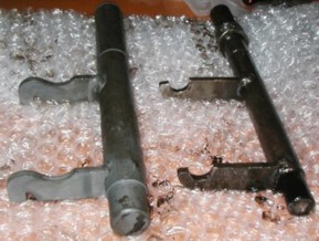
Another issue to be overcome is the larger shaft diameter of the later forks : this can be seen below.
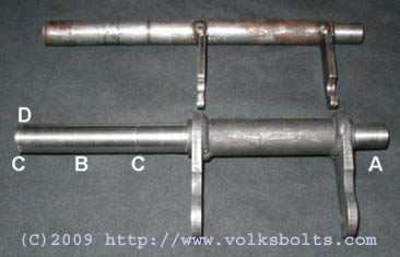
To make this larger clutch actuation shaft / forks combination fit our 1500 Beetle we had to arrange to have
some machining done. With reference to the below image :
- Machine back the later (thicker) shaft to the radius of the older shaft at the support bearing end.
- Machine back the later (thicker) shaft to the radius of the older shaft across the actuation lever and main support bearing end.
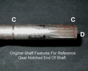
- Cut the circlip grooves back into the machined area
- Cut the toothed notches into the end of the shaft where the actuation lever fits and locks into place
(not shown in main photograph). These have to be cut by a gear-cutting machine.
Thats the actuation shaft and release forks now organised : now lets turn our attention to the guide sleeve options.
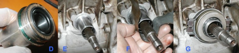
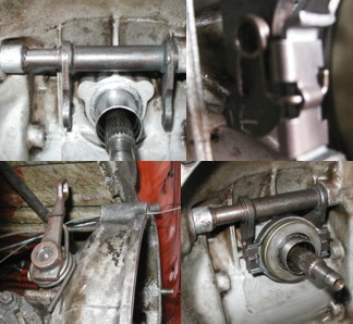
In the below picture we can see both options.
The left hand item is a guide sleeve that fits in place of the gearbox input shaft oil-seal. The old / original
oil-seal has to be removed and then this item pressed / tapped-in in its place. It contains a replacement oil-seal
as part of of the assembly (as can be seen in the picture).
The right hand item is a genuine guide sleeve as used by VW. This requires three(3) holes to be drilled and tapped
to take M7 studs. This item is then slotted over the studs and held down by 3 M7 nuts. The 1970 1500 gearbox casting
does have the bosses cast around the gearbox input shaft to facilitiate this installation - though other early
gearboxes may not.
As we lacked the appropriate jigging tools to enable accurate drilling of the holes for the studs we opted to use the
press-in guide-sleeve in place of the old gearbox input shaft oil-seal. Another consideration was the scarcity of
M7 thread taps, studs and nuts. M7 being a rather unusual and hard to source Metric size.
The removal sequence that we used for the old gearbox input-shaft seal and the installation sequence for the press-in
clutch release bearing guide is shown pictorially below with step-by-step annotation below that.
As we had no bearing / seal pullers that could get the behind the oil-seal to pull it out simply and cleanly we opted to
carefully hack-away at it until it collapsed such that we could remove it.
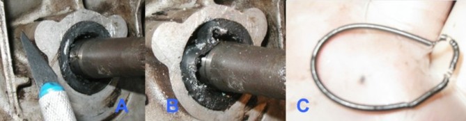
- Using a sharp craft knife cut away the rubber top-part of the old gearbox input shaft oil-seal to expose
the metallic sub-structure.
- Using a small drill bit (2mm in our case) drill into the metallic part of the oil seal so that the stucure
is weakened. We then used a small screwdriver and a peening hammer to collapse the outer wall of the seal as shown.
It can then be prised out.
Another more advisable option is to drill three 2mm holes and then install some Pan-Head self-tapping screws into the
seal. The screws then can be used to provide leverage to lift the seal out.
- Don't forget to make sure all parts and all debris are removed from the gearbox input shaft area - including the
spring tensioner from the old seal (as shown).
- The clutch release bearing guide sleeve was placed in a freezer over-night to shink it a few thousandths-of-an-inch
to aid with installation. Some sealant was also applied to the mating face to make sure the oil-sealing properties of the
assembly was fail-safed.
- A suitable drifting tool was used to drift the release bearing sleeve assy into position. It was a very tight fit
(interferance) as it transpired. Drift it all the way in to seal against the sealing flange.
- A quick rub-down with some oiled wet'n'dry / emery paper to de-burr the end of the guide sleeve prior to test-fitting
the release bearing. Make sure the oiled paper wraps around the circumferance to keep the action even.
Thoroughly clean the guide sleeve before offering the bearing up to it. Also make sure the input shaft splines are clean
and that all debris and dirt is removed from the bell-housing.
- Test fit the release bearing to make sure it fits snuggly and slides easily up and down the guide sleeve.
If the release bearing fit is too tight then step F can be repeated to remove a thou or two from the guide sleeve
outer diamter.
Now lets cover the removal and replacement of the clutch actuation shaft / arm itself....this is a little out of sequence
but the information should be useful to some of you out there.!
- Remove the clutch release bearing
- Disconnect the clutch cable.
Remove the circlip on the outside of the shaft where the clutch cable arm sits.
Remove the actuation arm and return spring.
- Slide the shaft over to the left and it will pop-out of the opposing support bearing.
Note : The gold coloured bushing / bearing restricts the play in the shaft preventing its removal at this point.
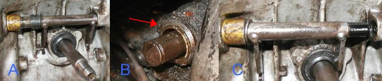
- Remove the retaining bolt that lurks behind the gold bushing in the bellhousing casting such that the bushing
is freed up for removal. Also arrowed in picture B.
- Tap the clutch actuation shaft against the bushing such that the bushing is forced to drift out of the bellhousing
casting.
- You may have to grip the bushing with mole-grips and pull it out to complete removal - as in our case. This
may be destructive to this bushing (as in our case) - replacements cost pennies though.
Now : the free play obtained on the actuation shaft by removing this bushing enables it to be removed.
Re-installation is a straight forward reversal of this sequence.
- Install the actuation shaft (reversal of above sequence)
- Install the release bearing - picture of retention clip as-installed is shown.
- Install actuation lever arm on the outside of the case (picture shows return spring partially installed).
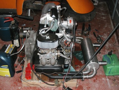
- The finished product (ready to install the engine below..!!
|
|