 Stainless Steel & High Tensile Steel Bolts & Quality Parts |
Home About Technical & FAQ How To Buy & Contact Terms & Conditions of Sale Links |
|


Product Catalogues
VW Split Screen Van
VW Bay Window Van
VW Beetle
VW Type 3
VW Thing / Trekker
VW Karmann-Ghia
VW Engines T1+T4
VW Electrical
IGNITION SYSTEMS
TOOLS
Product Catalogues
Air Cooled Porsche
Rover V8 Parts
Ford Kits
BMC Era Car Parts
Land Rover Kits
"Dog House" (Late 13/1600cc) Fanshroud Internal Cutaway
|
In Order To Better Understand The Cooling Requirements Of The VW Air-Cooled Engine You Have To Cut Up And Look Inside One Of The Fanshrouds. 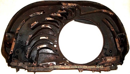 If We Turn This Into A Silhouette Showing The Ducting Blocked Out We Get : 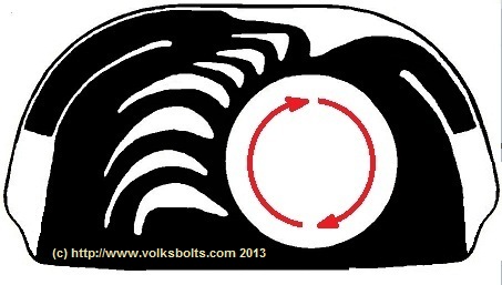 A Larger Picture Of The Cut Open Fanshroud Can Be Found In Our Main Drawing / Image Archive On This Web-Site. The Picture Was Taken As Per The View From The Pulley / Alternator Side Of The Engine. The Direction Of Fan Rotation Has Been Added For Clarity. The Black Space Represents The Air Cavities. Any White Space Is Sealed Unused Space Within The Fan Shroud. It Can Be Clearly Seen How VW Used Aerofoil Shaped Deflectors Inside The Fan Shroud To Manipulate And Duct The Air Towards The Cylinder Banks And Heat Exchanger Outlets. |
Thermostatic Flaps - Detail Of Delivery Of Air To Cylinder Banks
 Here We Can See That The Fan Shroud Centres On The Two Cylinders - Essentially Pouring The Cooling Air Down The Middle Of The Two Cylinders Such That It Cools Them Evenly. We Can Also See That Some Two-Thirds Of The Cooling Air Is Ducted Onto The Aluminium Cylinder Head, With The Remaining Third Being Ducted Onto The Top Of The Cast Iron Barrels Where The Fins Are At Their Largest. The Function Of The Thermostatically Controlled Stangler Flaps Is Also Clear. In The "Closed" Position They Arrest The Flow Of Cooling Air. In The "Open" Position They Sit At A 90 Degrees Angle To The Air-Flow, Thereby Permitting A Full Flow Of Cooling Air To The Cylinder Heads And Barrel Tops From The Fan. In Our Opinion, When The Thermostat Flaps Are In The "Open" Position, They Provide A Dividing And Ducting Function Such That A Final Correction Is Applied To The Air Flow Onto The Cylinder Head And Barrel Such That The Optimim Cooling Flow Of Air Enters The Finned Structures. Without This Final Correction The Inertial Centrifuge Effect Of The Main Fan On The Blown Air Would See It Forced More To The Outer Extremities Of The Containing Fanshroud Structure. 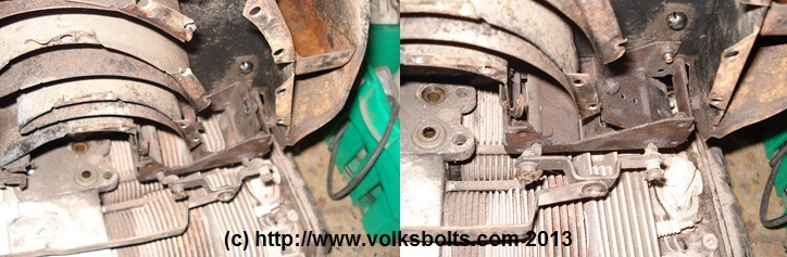 The Primary Observation We Make On This Side Of The Cooling System Is That The Fan Shroud Is Not Centred On The Two Cylinders : Cylinder 4 Accepts More Cooling Air Than Cylinder 3. This Arrangement Is Almost Certainly Why Cylinder 3 (And It's Valves / Piston Rings Etc.) Is Notorious For Being The One That Wears Out And Fails First. This Inequality Of Cooling Will Also Result In Differentials In Thermal Expansion Effects Between The Two Cylinders Which Can Cause Problems With Stresses / Strains Across The Sealing Face Of The Cylinder Head (In Addition To Uneveness Of Wear & Tear). In All Other Respects The Observations As Per Cylinder Bank Housing "1" & "2" Apply. Number "3" Running HOT May Also Lead To Problems In This Cylinder With Pinking / Detonation / Pre-Ignition Etc. @ There Is Some Anecdotal Evidence That VW Retarded The Ignition On This Cylinder Slightly To Ease This Problem. This Would Have Been Done Via The Shaping Of The CAM Lobes That Drive The Contact Breaker Points Inside The Distributor. |
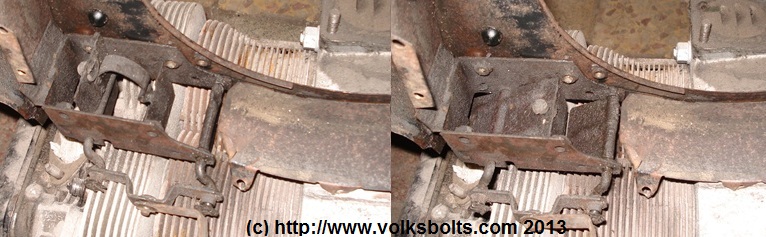
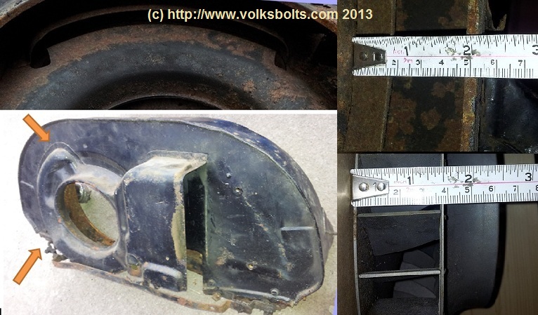 In The Above Photograph We Can See The Extra Piece Of Steel Ducting That Is Designed To Bleed Air Off The Main Fan And Duct It To The "Dog House" Style Oil Cooler. As Can Be Seen, Highlighted Between The Two Arrows And Next To The Tape Measure, The Bleed Air Is Scavenged From The Feed To Cylinder Bank Housing "1" & "2" By A Long Thin Scoop That Protrudes Through From The Back Of The Fan Shroud. This Will Divert Some Cooling Away From Cylinder "1", Unbalancing The Cooling Of This Bank Slightly. The Scoop Diverts Approximately One-Third (1/3) Of The Fan Air In The Area That It Is Located. We Included A Picture Of The 1600cc Engine Fan For Completeness. |
Percentage Breakdown Of Delivered Air
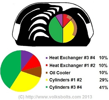 To Generate The Above Graphic We Have Divided The Air-Flow From The Fan Into Its Zones Of Utilisation. We Then Took Measurements And Used Some Trigonometry Such That We Could Calculate The Percentages. It Can Be Seen That The Heating System Takes Approx 20% Of THe Fan Air (10% Into Each Heat Exchanger). The Oil Cooler Also Takes About 10%. The Cylinder Bank That Is Blown Down The Middle (#1 & #2) Takes 30% Of The Fan Air. The Cylinder Bank With The Offset Cooling (#3 & #4) Takes 40% Of The Fan Air : We Feel That This Elevated Flow Offsets The Losses Due To Having To Duct And Turn The Air In Addition To Compensating Somewhat For The Offset In The Blowing Of The Two Cylinders. |
Review Of Type4 (Porsche 914 & VW Van \ 411) Cooling System
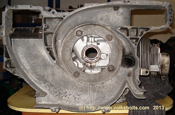 As Can Be Seen In The Above Photograph, Taken From The Fanshroud Side Of The Engine With The Fanshroud Opened So We Can See Inside, The Type4 Engine Cooling System Utilises A Fan Directly Driven Off \ Bolted To The End Of The Crank Shaft. The Fan Is Of Centrifugal Type With The Overall 'Snail Shell' Design Being Reminiscant Of A Turbo Charger. As Per The Type1 (Beetle) Engine There Are Two Cylinder Banks (#1 & #2 Cylinders) (#3 & #4 Cylinders), Two Heat Exchanger Outlets And Provision For The Cooling Of Oil Via An Outlet To The Oil Cooler. For The Sake Of This Article We Will Ignore The Small Black Tube Adjacent To Cylinders #1 & #2. The Black Flap Visible Adjacent To Cylinders #3 & #4 Is Thermostatically Controlled And Is One Of A Pair That Arrests Air Flow To The Cylinder Banks When The Engine Is Cold; In The Same Fashion As The Thermostatically Controlled Flaps On The Type1 (Beetle) Engine. On The Type4 Engine The Thermostat Flap Also Arrests Air Flow To The Oil Cooler When The Engine Is Cold. This Arrangement Is Shown In The Below Pictures. 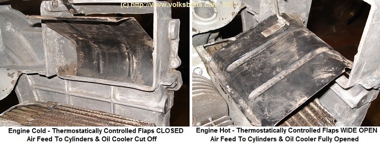 |
Percentage Breakdown Of Delivered Air : Type4 Cooling System
|
As Blown Air Is Delivered Circumferentially From A Centrifugal Fan We Can Simply Draw Lines From The Origin
Of The Fan Circle To Cover The Outlet Zones Of The Blown Air Outlets. We Can Then Take Measurements And Use Some Trigonometry Calculations
To Work Out The Percentages In The Below Graphic. 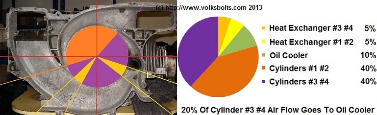 It Can Be Seen That The Heating System Takes Approx. 10% Of The Fan Air (5% Into Each Heat Exchanger). The Oil Cooler Also Takes About 10%. Each Cylinder Bank Of The Type4 Takes Approximately 40% Of The Blown Fan Air - As Per Cylinders #3 & #4 On The Type1 Design. Interestingly, The Heating System Takes A Lower %age Of The Blown Fan Air On The Type4. This May Be Because The Fan Is Of A Higher Output Design : Though More Slowly Rotating As It Is Direct Driven By The Crank And Not "Ratio" Driven By A Vee Belt Like On The Type1 Design. |