 Stainless Steel & High Tensile Steel Bolts & Quality Parts |
Home About Technical & FAQ How To Buy & Contact Terms & Conditions of Sale Links |
|


Product Catalogues
VW Split Screen Van
VW Bay Window Van
VW Beetle
VW Type 3
VW Thing / Trekker
VW Karmann-Ghia
VW Engines T1+T4
VW Electrical
IGNITION SYSTEMS
TOOLS
Product Catalogues
Air Cooled Porsche
Rover V8 Parts
Ford Kits
BMC Era Car Parts
Land Rover Kits
US Federal Law On Seat Belt Hardware
|
US Dept ofTransportation : Federal Motor Carrier Safety Administration |
Basic Interpretation Of US Law
First of all we need to put the Seat-Belt Bolt loading into perspective by calculating the G-Force deceleration implied by the requirement. If we assume a hefty 250lb+ individual is being restrained by the Seat-Belt :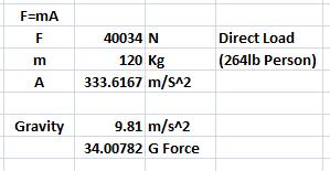 So we can see that we have a 34G loading (this figure would rise for a smaller weight of restrained occupent) - which for all intents and purposes is the loading induced by a severe crash.! This is the equivalent of going from approx. 800mph to zero in a single second.!! Or driving into a brick wall at 40mph (arresting to zero in 0.05 of a second).! FURTHER : It should be remembered that most Seat-Belts are 3-Point types - so there would be 3 bolts/nuts taking the load of the 'shock' deceleration - the above calculation is assuming ALL of the occupents decelerative Mass is focused onto the one bolt. For the purpose of the making the following calculations we have to resolve the input force (at 45 degrees application angle) into a shear loading and a tensile loading component. 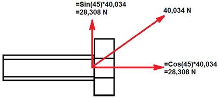 |
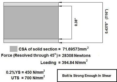
Shear Calculation on 304 (A2-70) Bolt
Calculations / Unit Conversions from Imperial to Metric not shown for brevity.
 |
Thread Loading Calculation on 304 (A2-70) Bolt
First of all let us consider the basic UNF threadform :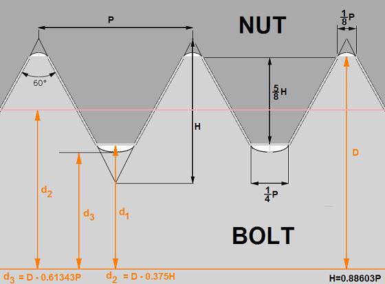 First Pass : consider the traditional STRESS AREA of the thread under TENSILE loading (As) : 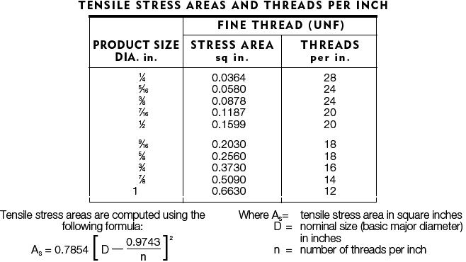 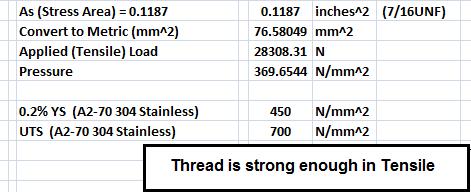 Second Pass : consider the first Turn of Thread Loading ONLY : There is a widespread assumption that each turn of thread in a nut and bolt will take and hold an equal share of the load applied. Therefore, the assumption goes - to handle higher loads one simply increases the length of engaged turns of thread. In reality it is found that the first turn of engaged thread presented to the load will be subjected to the highest load, with each subsequant turn of thread handling proportionally less and less, with their being no net advantage to engaging over one (1) nominal shank diameter worths of thread (approximatley six (6) turns). This extends out to 1.5 shank diameters of threading in Aluminium. This is envisaged diagramatically below : 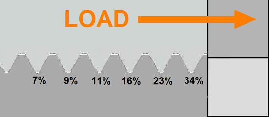 So what we need to do now is calculate the surface area of the loaded section of a single thread - we can do this using the data provided above as its simply the surface area of two cones (one subtracted from another). We can also resolve the Force so it is presenting itself perpendicular to the loaded face of the material (both full Force AND resolved Force can have pressure loading calculations - that part is easy inside a spreadsheet.! 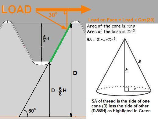 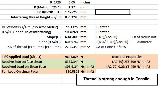 |
Conclusion On Theoretical Component
|
Two independant theoretical calculation pathways have been used to demonstrate that an A2-70 graded Stainless Steel bolt is strong enough to be used for mounting seatbelts. This succesful theortical outcome needs to be validated by hardware testing such that the US Federal Law used as the governing requirement can be satisified FULLY. |